Most motherboards have between 4 and 14 USB ports on the rear I/O panel, depending on form factor and chipset tier. An ATX motherboard typically offers 8–12 rear ports, while a Mini-ITX board may provide only 4–6. When you add internal USB headers which route additional ports to your PC case’s front panel total system capacity commonly reaches 15 to 20+ connections.
The exact number depends on three factors: the board’s physical size, its chipset generation, and how many internal headers the manufacturer included. This guide breaks down each variable so you can accurately assess your system’s true USB capacity and expand it if needed.
While counting the rectangular slots on the back of your PC is easy, understanding your motherboard’s true USB capacity requires looking deeper. Modern peripherals from 4K webcams to high-polling-rate gaming mice and audio interfaces demand massive data throughput.
This guide breaks down exactly how many ports your system can support, how to identify them, and why plugging in too many devices might cause a bandwidth bottleneck.
How to Check How Many USB Ports Your Motherboard Has
Before buying a hub or expansion card, confirm what your current board actually provides. There are three reliable methods.
Method 1: Check the Manufacturer’s Specification Page Every motherboard has a product page on the manufacturer’s website (ASUS, MSI, Gigabyte, ASRock) listing exact port counts, types, and header configurations. Search your board’s model number followed by “specifications.” This is the most accurate source.
Method 2: Use Windows Device Manager Press Windows Key + X, select Device Manager, and expand Universal Serial Bus controllers. Each “USB Root Hub” entry represents an active controller. This shows you how many controllers are running, though it will not distinguish between rear and front-panel ports.
Method 3: Physical Inspection Count the rectangular and oval ports on your rear I/O panel directly. Use the color guide in the section below to identify each port’s speed rating. Then open your case and locate the internal headers on the motherboard these are groups of exposed pins labeled “USB2_0”, “USB3_0”, or “USB3_C” in the board’s silkscreen printing.
Physical inspection combined with the manufacturer spec sheet is the only method that gives you a complete picture of both active ports and unused header capacity.
The Motherboard Form Factor Matrix: How Size Dictates Capacity
The physical size of your motherboard directly limits how many USB ports and internal headers it can house. Larger ATX boards offer maximum connectivity with multiple host controllers, while compact Mini-ITX boards sacrifice port volume to save physical space.
To understand your baseline capacity, you first need to identify your motherboard’s form factor.
| Motherboard Form Factor | Avg. Rear I/O Ports | Avg. Internal Headers | Total Potential Ports | Best Use Case |
|---|---|---|---|---|
| E-ATX (Extended) | 10 – 14 | 4 – 6 | 18 – 24+ | Extreme workstations, dual-PC streaming setups, heavy peripheral users. |
| ATX (Standard) | 8 – 12 | 3 – 5 | 14 – 20 | High-end gaming, content creation, standard desktop towers. |
| Micro-ATX (mATX) | 6 – 8 | 2 – 3 | 10 – 14 | Budget gaming builds, compact office workstations. |
| Mini-ITX | 4 – 6 | 1 – 2 | 6 – 10 | Small Form Factor (SFF) living room PCs, portable gaming rigs. |
Note: Premium chipsets (like Intel Z790 or AMD X870E) will generally populate these form factors with higher-speed ports than budget chipsets (like B760 or A620).
How Your Chipset Determines USB Port Allocation
The chipset acts as a traffic manager between your CPU and the rest of the motherboard. Higher-tier chipsets receive more USB lanes from the processor, which gives manufacturers the physical capacity to populate boards with more high-speed ports.
Intel’s Z790 chipset, for example, supports up to 10 USB 3.2 Gen 2 ports natively, while the budget B760 chipset supports fewer high-speed allocations and relies more heavily on USB 2.0 connections for auxiliary functions. AMD’s X870E chipset similarly provides more USB4 40 Gbps allocations than the entry-level A620.
In practical terms: two motherboards of identical physical size can have meaningfully different port counts and speeds purely because of chipset tier. A $150 mATX board on a B760 chipset will have fewer and slower ports than a $300 mATX board on a Z790.
Rear I/O Ports vs Internal USB Headers (What is the Difference?)
A rear I/O USB port is a physical, external slot on the back of the motherboard ready for immediate device plug-in. An internal USB header is a cluster of bare pins on the motherboard circuit board used to route additional USB ports to your PC cases front panel.
Many first-time PC builders look at the back of their case, count 6 ports, and assume that is their absolute limit. In reality, your motherboard has hidden capacity via internal headers.
- 9-Pin Headers (USB 2.0): These support up to two USB 2.0 ports each. They are critical for modern aesthetics, as they power internal components.
- 20-Pin Headers (USB 3.2 Gen 1): These chunky, rectangular headers route high-speed (5 Gbps) blue USB ports to the top or front of your PC case.
- Key-A Headers (Type-C / USB 3.2 Gen 2×2): The newest internal connector, designed specifically to route a high-speed, fast-charging USB-C port to your front panel.
The Builder’s Corner: The AIO Header Trap
In my last dozen workstation builds, I routinely encountered the 9-pin header trap. Modern motherboards often only include two USB 2.0 internal headers. However, if you are installing an AIO liquid cooler, an RGB lighting controller, and a smart fan hub, you suddenly need three headers. If you run out, your front-panel case ports will remain dead unless you buy an internal USB 2.0 splitter. Verified through repeated observation across workstation builds using ASUS ProArt, MSI MEG, and Gigabyte Aorus platform motherboards.
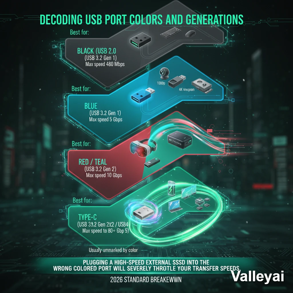
Decoding USB Port Colors and Generations
Motherboard manufacturers use color-coding to indicate the speed and generation of a USB port. Black ports are standard USB 2.0, blue ports indicate USB 3.0 (5 Gbps), red or teal ports signify USB 3.2 Gen 2 (10 Gbps), and Type-C ports offer the fastest data delivery.
Plugging a high-speed external SSD into the wrong colored port will severely throttle your transfer speeds. Here is the 2026 standard breakdown:
- Black (USB 2.0): Max speed 480 Mbps. Max power: 500mA (2.5W). Best for keyboards, mice, and older printers.
- Blue (USB 3.2 Gen 1): Max speed 5 Gbps. Max power: 900mA (4.5W). Best for 1080p webcams, flash drives, and basic external storage.
- Red / Teal (USB 3.2 Gen 2): Max speed 10 Gbps. Max power: 900mA standard, up to 3A with Power Delivery negotiation. Best for 4K webcams, VR headsets, and fast NVMe external drives.
- Type-C (USB 3.2 Gen 2×2 / USB4 / Thunderbolt 4 & 5): Max speed 20 Gbps to 80 Gbps. Max power: up to 240W with USB Power Delivery 3.1. Reserved for high-wattage charging, daisy-chaining monitors, and ultra-fast data arrays.
Thunderbolt vs USB4 note: Thunderbolt 4 and 5 ports use the same physical USB-C connector but are certified by Intel and support additional protocols including DisplayPort tunneling and PCIe tunneling. A USB4 port and a Thunderbolt 4 port look identical check your motherboard specification sheet to confirm which standard your Type-C ports support before purchasing Thunderbolt-specific accessories.
The Bandwidth Bottleneck: How Many USB Devices Can One Motherboard Handle?
What is a USB host controller? A USB host controller is a dedicated chip on your motherboard that manages communication between the CPU and a group of USB ports. Each controller has a fixed bandwidth ceiling determined by how many PCIe lanes connect it to the processor. Modern motherboards use the xHCI (Extensible Host Controller Interface) standard, which Intel introduced to unify USB 2.0, 3.0, and later generations under a single controller architecture.
Multiple physical ports on your rear I/O panel typically share one of these controllers. That means the total bandwidth available to four 10 Gbps ports routed through a single controller is not 40 Gbps it is capped by the PCIe lane feeding that controller, which is often a single x1 lane (approximately 8 Gbps in PCIe 3.0).
You’ve plugged in 10 devices a 4K webcam, an audio interface, external SSDs, and racing peripherals. Suddenly, your mouse starts stuttering and your webcam drops frames. Why? Because you’ve hit a bandwidth bottleneck.
While a motherboard might physically have 12 USB ports, it does not mean it can run 12 high-bandwidth devices simultaneously at full speed. This is the difference between physical ports and USB Host Controllers.
Multiple USB ports on your rear I/O panel often share a single host controller. If four 10 Gbps ports are routed through a controller that only has a single PCIe lane connecting it to the CPU, the total combined bandwidth of those four ports cannot exceed the limit of that lane.
Pro-Tip for Power Users: If you are running bandwidth-heavy devices (like multiple capture cards or VR sensors), spread them out. Plug one into the front panel (which usually runs off the chipset) and one into the rear panel (which often runs directly to the CPU) to split the controller load.
How to Add More USB Ports to Your Motherboard
To add more USB ports to your motherboard, you can install a PCIe USB expansion card, connect a powered external USB hub, or utilize internal USB header splitters. The best method depends on your available PCIe slots and power requirements.
If you have reached your motherboard’s native limit, here is how you safely expand your capacity:
Step 1: Assess Your PCIe Slot Availability
If you have an empty PCIe x4 or x1 slot beneath your graphics card, a PCIe USB Expansion Card is the best solution. Because this card plugs directly into the motherboard’s PCIe lanes, it provides its own dedicated USB controller, bypassing any existing bandwidth bottlenecks.
Step 2: Utilize a Powered External Hub
If you cannot open your case or lack PCIe slots, use a Powered USB Hub. Do not use a cheap, passive “dongle” splitter for multiple devices. A powered hub plugs into a wall outlet, ensuring that power-hungry devices (like RGB keyboards or external hard drives) do not overdraw current from your motherboard’s VRMs, which can cause system instability or phantom disconnects.
Step 3: Expand Internal Headers
If your front panel ports are dead because you ran out of connections for your RGB fans, purchase an Internal USB 2.0 Hub (like those made by NZXT or Corsair). This acts as a splitter inside your case, turning one motherboard header into three or four.
Frequently Asked Questions
How do I check my motherboard USB port count without opening the case?
You can check your active USB controllers using Windows Device Manager. Press the Windows Key, type Device Manager, and expand the Universal Serial Bus controllers drop-down. Counting the USB Root Hubs will give you an idea of how many active controllers your system is running, though physical inspection or checking your exact motherboard manual online is the only way to get a perfectly accurate physical port count.
Can I add more USB ports to my motherboard?
Yes. You can add more ports by installing a PCIe expansion card directly into the motherboard, connecting a powered external USB hub to an existing high-speed port, or using internal header splitters to activate unused ports on your PC case.
What is the difference between a USB port and a USB header?
A USB port is the finished, rectangular (or oval) external slot where you plug in a device like a mouse or flash drive. A USB header is a cluster of exposed metal pins located directly on the motherboard circuit board, which requires a cable to bridge it to a usable port on the front of your PC case.
Why does my motherboard have different colored USB ports?
Motherboards use colors to visually communicate the maximum speed of the port. Black typically means standard USB 2.0, blue means USB 3.0 (5 Gbps), and red or teal indicates high-speed USB 3.2 (10 Gbps). Plugging high-speed devices into black ports will limit their performance.
How many USB devices can one motherboard handle?
Theoretically, the USB protocol allows for up to 127 devices to be daisy-chained to a single controller. However, in reality, a standard motherboard can practically handle between 10 to 15 active devices before encountering severe power delivery issues or bandwidth bottlenecks (stuttering, disconnecting), depending on how much data and power each device requires.
What is a USB host controller?
A USB host controller is a chip on your motherboard that manages data traffic between the CPU and a set of USB ports. Multiple ports typically share one controller, which means those ports share a single bandwidth ceiling rather than each receiving full independent speed. When several high-bandwidth devices share one controller simultaneously, performance degrades across all of them.
Does my chipset affect how many USB ports I have?
Yes, directly. Higher-tier chipsets (Intel Z790, AMD X870E) allocate more USB lanes and support more high-speed port configurations than budget chipsets (B760, A620). Two motherboards of the same form factor can have different port counts and speeds entirely because of chipset differences. Always check the chipset specifications alongside the motherboard’s own spec sheet.
Why are some of my USB ports not working?
Three common causes: the port is disabled in BIOS/UEFI (check USB configuration settings and enable any ports listed as “Disabled”), the internal header cable is not fully seated on the motherboard pins (reseat the front-panel USB connector), or the port has failed due to power surge damage. If Device Manager shows the port as an “Unknown Device” with a yellow warning icon, a driver reinstall or BIOS update may resolve it.
Kaleem
My name is Kaleem and i am a computer science graduate with 5+ years of experience in Computer science, AI, tech, and web innovation. I founded ValleyAI.net to simplify AI, internet, and computer topics also focus on building useful utility tools. My clear, hands-on content is trusted by 5K+ monthly readers worldwide.