

Every fiber link starts the same way. A laser fires a pulse of light into a strand of glass thinner than a human hair. The pulse travels inside the strand’s core, its innermost layer, and it stays in the glass until a receiver at the far end collects it.
Total internal reflection keeps the pulse inside. Inside the core, light runs straight until it reaches the boundary with the cladding, the glass layer that wraps the core. There it reflects back inward. The bounce repeats along the whole strand, around bends in a city duct and across the floor of an ocean.
How Glass Traps Light?
Refractive index sets the trap. The number says how much a material slows light, and the core carries an index near 1.468 against the cladding’s 1.462. Crossing from the higher index to the lower one, light bends away from the normal, the line drawn square to the surface. Past a certain angle, it stops crossing at all and reflects completely. Snell’s law gives that angle as the inverse sine of the cladding index over the core index. For the typical pair 1.468 and 1.462, two values chosen to stand in for a standard telecom fiber, the critical angle is 84.82 degrees from the normal, or 5.18 degrees from the fiber axis. Rays running within 5.18 degrees of the axis stay trapped. Steeper rays leak into the cladding and are lost.
Two rules follow from that bounce, and they decide everything about a fiber. Match the fiber to the distance: single-mode for anything beyond a building, multimode inside one. Judge a home plan by its slowest link, because the plan speed is a ceiling on traffic leaving the home, never a promise at the screen.
One widely read explainer states the critical angle as about 42 degrees for a typical glass fiber. That number is the critical angle for glass against air: the inverse sine of 1 over 1.5 is 41.81 degrees. It is the wrong boundary for a fiber. The same page lists core and cladding indices of 1.447 and 1.444, and those give a critical angle of 86.31 degrees. Those two numbers differ because the boundary changed. Against air, glass traps light at 42 degrees. With glass on both sides and indices only 0.2 percent apart, the angle is about 86 degrees. A reader who takes the 42-degree figure into a fiber design aims the light far too steeply and loses it.
Why does the light not escape through the side of the glass? It meets the wall at an angle the glass cannot pass. Every ray that counts runs within 5.18 degrees of the axis, so every meeting with the wall happens beyond the critical angle, and the reflection is total. No coating holds the light in. The cladding is transparent glass, and the boundary between two glasses does the work.
A flat stone thrown across a pond behaves the same way. Flung flat, it skips from the surface again and again. A steep throw plunges on the first hit. The angle decides, and the pond needs no mirror to send the stone back. A fiber needs no mirror either. Its wall is bare glass.
The fiber is solid glass from core to jacket. No hollow tube runs down its middle, and no mirror lines its wall. The cladding is a second glass, slightly different from the core, and that small difference is what traps the light.
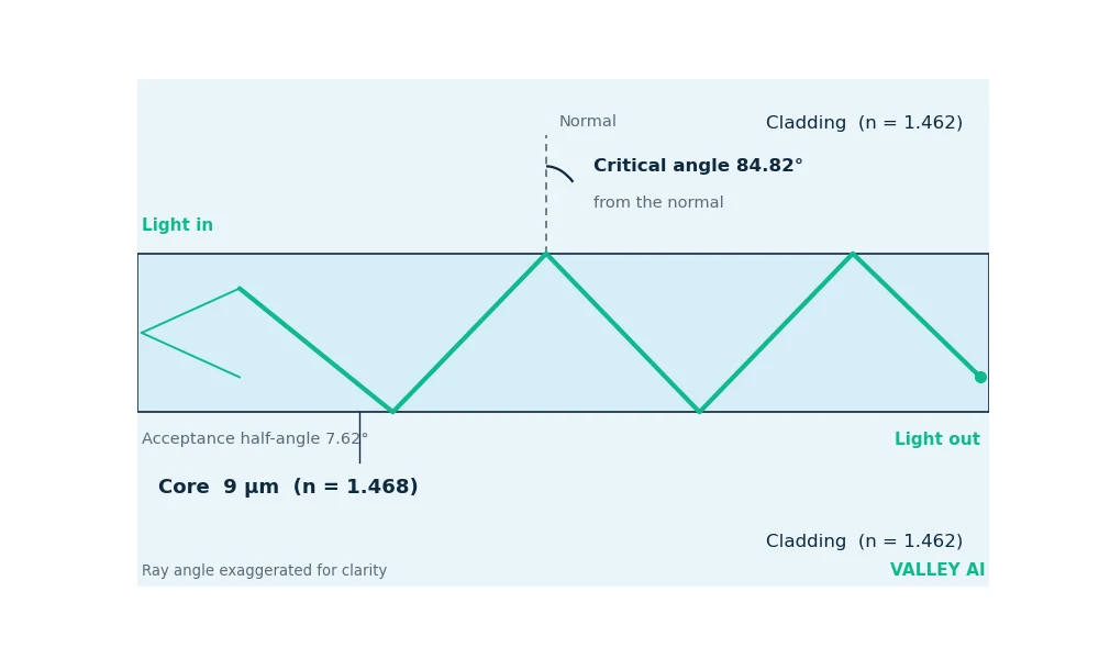
Light has to enter at the right angle. The cone of entry is narrow: the numerical aperture of the typical pair is 0.1326, which gives an acceptance half-angle of 7.62 degrees in air. A ray arriving outside that cone hits the wall too steeply and leaks out on the first bounce. The launch lens sets the cone, and a dirty connector face scatters light outside it.
One Pulse Across the Atlantic
The MAREA cable runs 6,600 kilometers from Virginia Beach to Sopelana, near Bilbao, on the floor of the Atlantic. Microsoft and Facebook funded it, Telxius operates it, and its design capacity is 200 terabits per second across eight fiber pairs. One pulse of light makes the crossing in about 32 milliseconds. The numbers behind that trip show what a fiber can do and what it cannot.
- A laser at the Virginia Beach landing station flashes on and off billions of times a second, coding bits as light.
- A lens launches the light into the core inside the acceptance cone.
- The pulse travels at 204,190.0 kilometers per second, 68.1 percent of light speed in vacuum.
- Optical amplifiers boost the pulse about every 80 kilometers, because the glass absorbs and scatters a little of it on every kilometer.
- A photodetector near Bilbao turns the flashes back into an electrical signal.
Light needs 32.32 milliseconds to cover 6,600 kilometers at 204,190.0 kilometers per second. The round trip takes 64.65 milliseconds. Loss is the harder number. At the datasheet maximum of 0.18 decibels per kilometer, 6,600 kilometers cost 1,188 decibels, which would leave nothing at all. Amplifiers spaced 80 kilometers apart split the crossing into about 82 spans, and each span loses about 14.4 decibels, a loss the next amplifier makes up.
Those figures, calculated 14 November 2026, carry their limits with them. The 32.32 milliseconds counts light travel alone, and the cable route runs longer than the straight-line distance. Electronics at each end add their own time, so a real round trip runs longer than 64.65 milliseconds. The 80-kilometer spacing is a chosen midpoint of the usual 50 to 100 kilometer range, and a real cable varies its spacing along the route. The 0.18 decibel figure is a datasheet maximum, so a good span loses less. The trip time is a floor. Real trips run longer.
Capacity comes from color. A modern system sends many wavelengths down one fiber at once, each carrying its own stream. Eighty channels at 100 gigabits per second give 8 terabits per second on a single fiber. MAREA carries 200 terabits per second across eight fiber pairs, or 25 terabits per second per pair. A 2021 field trial pushed one wavelength on MAREA to 700 gigabits per second, and the fiber carried it without change.
Single-Mode and Multimode: Two Fibers for Two Distances
Two fibers cover every job, and the core diameter decides which one fits. Single-mode fiber carries one path of light down a core nine micrometers wide. Multimode fiber carries many paths down a core 50 or 62.5 micrometers wide. The table sorts them by the question that decides the pick: how far the light has to go.
| Property | Single-mode | Multimode |
|---|---|---|
| Core diameter | 9 micrometers | 50 or 62.5 micrometers |
| Light source | Laser, 1310 or 1550 nm | LED or laser, 850 nm |
| Paths | One | Many |
| Distance | 100 km or more without amplification | Up to 2 km |
| Best for | Long-haul links, submarine cables, fiber to the home | Data centers, buildings, campuses |
Does light really travel in a straight line inside a single-mode fiber? It travels in one mode, which is as close to a straight line as a guided wave gets. The core is too narrow for a second path, so every part of the pulse arrives at the same time. The zigzag picture belongs to multimode fiber, where many paths bounce down a wide core at different angles.
Those paths cost time. The steepest ray in a 50-micrometer multimode core bounces about 3,322 times per meter, worked from a typical 1.48 core and 1.46 cladding, and each bounce adds a little distance. Rays that take the long way arrive later than rays that take the short way, and the pulse spreads. The spread is called modal dispersion, and it is the reason multimode links stay short. Graded-index fiber bends the rays in smooth curves instead of sharp bounces, which cuts the spread, but the limit stays: multimode serves buildings, single-mode serves cities.
What Wears a Pulse Down?
Glass looks clear, and it still steals a little light on every kilometer. Rayleigh scattering throws light sideways off density ripples frozen into the glass. Absorption takes light at impurity bands, worst at the water peak near 1,383 nanometers. Splices and connectors add their own small losses at every joint.
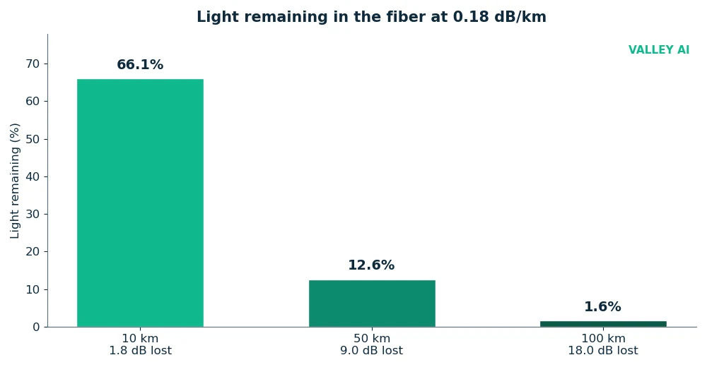
Corning’s SMF-28 Ultra datasheet caps the total at 0.18 decibels per kilometer at 1,550 nanometers. The table shows what that cap leaves behind after 10, 50, and 100 kilometers.
| Distance | Loss at 0.18 dB/km | Light remaining |
|---|---|---|
| 10 km | 1.8 dB | 66.1% |
| 50 km | 9.0 dB | 12.6% |
| 100 km | 18.0 dB | 1.6% |
Dispersion spreads a pulse a second way. Different wavelengths travel at slightly different speeds, so a pulse made of several wavelengths arrives smeared. The datasheet caps chromatic dispersion at 18 picoseconds per nanometer-kilometer at 1,550 nanometers. Over 100 kilometers, a source one nanometer wide spreads by 1.8 nanoseconds. At 10 gigabits per second, one bit lasts 100 picoseconds, so that spread covers 18 bit periods. The 1-nanometer width is a chosen input for the arithmetic; a real laser line is far narrower, and the spread shrinks with it.
Bends leak light a third way. A ray that met the wall beyond the critical angle on a straight run meets it below the angle once the fiber curves, and the light escapes. Corning rates the fiber at a 10-millimeter bend radius for one turn, with at most 0.50 decibels of added loss. The rating for ten turns at a 15-millimeter radius is at most 0.05 decibels. A cable coiled tight around a nail breaks the rule by a wide margin, and the signal fades with the bend.
Two checks need no instruments. The connector on a fiber patch cable is blue or green, and the color is a fact: blue marks a flat UPC polish, green marks an angled APC polish. A blue connector mated to a green port reflects light back and costs signal, so the colors must match. The second check sits on the ONT, the box where the fiber enters the home. A red LOS light means the fiber signal is gone. A tight bend or a loose connector sits behind most such failures, and straightening the cable is the first thing to try.
The Last Meters: From the Street to Your Screen
At the end of the run, the ONT turns light back into electrical signals. It is the fiber counterpart of a modem, and the modem guide sets out what a fiber ONT does differently.
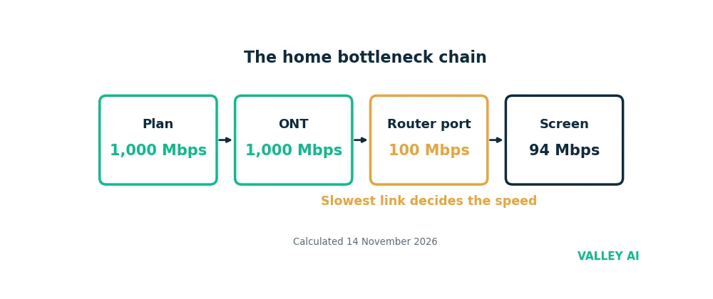
From the ONT, the signal crosses four more links before it reaches a screen: the ONT port, the router, the cable or Wi-Fi, and the device itself. Each link sets a ceiling. The plan caps traffic leaving the home, while the local link caps traffic inside the home. A gigabit plan does not make a 100-megabit port faster. A fast port does not fix a weak Wi-Fi signal.
If the plan says 1 Gbps, why does a speed test show 94 Mbps? The test measures the slowest link in the chain, and the slowest link is often a port. A router with a 100-megabit LAN port caps every wired device at that port, and a 100-megabit Ethernet link carries about 94 megabits per second of real TCP throughput once the frame overhead is counted. The fiber delivered a gigabit to the ONT, and the port passed 94 megabits to the screen.
Cables set their own ceilings. A Cat5e cable carries a gigabit, and the cable categories and their ceilings are set out in how Ethernet works. A Cat6 cable carries 10 gigabits over short runs. An old Cat5 cable caps the link at 100 megabits, and it looks identical to the newer ones from the outside. The print on the jacket tells them apart.
Wi-Fi is usually the last ceiling. A Wi-Fi 5 link in a real home delivers a few hundred megabits per second. A Wi-Fi 6 link does better only when the router and the device both support it. The router’s port still binds the whole chain, and how a router works sets the wired ceiling: a gigabit plan behind a 100-megabit WAN port measures 94 megabits on every device, wired or wireless. When to plug in and when to stay wireless compares the two last links.
The first packet the fiber carries for most pages is a DNS lookup. The fiber moves the question to a resolver, and how DNS finds a website decides which server the browser talks to.
How a Fiber Is Made
A fiber starts as a preform, a glass rod about a meter long and a few centimeters thick. Modified chemical vapor deposition builds it layer by layer: gases flow through a silica tube while a flame heats it, and silicon and germanium react with oxygen to deposit glass on the tube’s inner wall. The tube collapses into a solid rod, and the rod carries the exact index profile the finished fiber needs.
The rod goes into a drawing tower and heats to about 2,000 degrees Celsius until the tip softens. Gravity pulls the molten glass down into a thread, and a tractor pulls the thread onto a spool at up to 20 meters per second. A laser micrometer measures the diameter as it draws and feeds the reading back to the tractor, so the finished strand stays even over kilometers. The protective coating goes on in the same pass, before the glass can pick up a scratch.
Purity is the point of all that care. In 1966, Charles Kao and George Hockham showed that the losses in early fibers came from impurities in the glass. The glass itself was clear enough, and purer glass could carry light for kilometers. Corning made the first low-loss fiber in 1970. Kao took half of the 2009 Nobel Prize in Physics for the work.
What Else the Glass Does
Most of the world’s fiber lies on the seabed. TeleGeography’s 2026 submarine cable map counts 694 cable systems and 1,893 landing stations, and the cables carry over 99 percent of intercontinental data traffic. The figure covers traffic between continents. It says nothing about every byte the internet moves, and its precise share is an estimate built on old FCC figures for satellite capacity. The broad conclusion stands: the internet crosses oceans on glass. Satellites carry well under 1 percent of that traffic.
The same physics serves other jobs. Ordered bundles of fibers carry images out of endoscopes, so doctors see inside the body through a small opening. Fibers embedded in bridges and pipelines sense strain and temperature along their whole length, because stretching or heating a fiber changes how light travels through it. Plastic fibers distribute light in cars and dashboards, where the heat source stays away from the visible output.
Hollow-core fiber is the next step. Researchers at the University of Southampton made fibers that guide light through air instead of solid glass, reaching 0.14 decibels per kilometer and sending signals about 45 percent faster than standard glass fiber. The glass is still a guide, but the light spends its trip in air. The fibers are research hardware today. Cables in the ground still use solid glass, and the gap between the two is manufacturing at scale.
Three questions settle whether fiber is the right order. Does the glass reach the home, or does coaxial cable cover the last meters? Which speed does the plan cap, and does the router carry a port to match it? Does the plan upload as fast as it downloads, since a shared fiber line often uploads slower? The answers decide the order. The fiber itself is rarely the limit.
Frequently asked questions
Can fiber optic cables carry electricity?
No. The core and cladding are glass, and glass is an insulator. A fiber carries light. It carries no current, which is why it cannot spark, cannot pick up a ground loop, and cannot be tapped by induction the way copper can.
Is fiber better than cable internet?
For the line itself, yes. Fiber carries more data, further, with less loss, and it ignores electrical interference. Cable still wins on one point: it is already in most homes, so it needs no new wire. The choice is usually decided by what reaches the house.
Why is upload slower than download on some fiber plans?
Many shared fiber lines split capacity unevenly. A GPON line, the common shared design, offers about 2.5 gigabits per second down and 1.25 gigabits per second up, shared between homes. A newer XGS-PON line offers 10 gigabits per second in both directions. The split comes from the plan. The glass carries whatever the plan gives it.
Can bending a fiber cable break the signal?
Yes. A bend tighter than the rated radius lets light hit the wall below the critical angle, and the light leaks out. The fix is simple: give the cable a gentle curve and never fold it sharply, and check the connector is seated if the signal drops after moving furniture.
Does fiber internet work during a power cut?
The glass keeps carrying light, but the ONT at the home needs mains power to turn that light into an electrical signal. A power cut takes the connection down unless the ONT has a battery backup. The amplifiers along a long-haul cable draw power through a copper conductor inside the cable, so the light path depends on the grid at both ends.
How long does a fiber cable last?
The glass does not corrode and does not wear out from carrying light. Installed fiber lasts decades; the lasers, amplifiers, and ONTs around it get replaced as electronics improve. A cable buried or laid on the seabed usually fails from anchors and fishing gear. Age alone rarely breaks one.

Kaleem
Kaleem is a Computer Science graduate (Virtual University of Pakistan) and the founder and editor of Valley AI, where he publishes in-depth, tested guides on computer hardware, artificial intelligence, and how the internet works. Every guide is researched from primary sources, tested hands-on where possible, and updated when the facts change.